Texas Offshore Miocene Project, Task 5.2
Caprock Seal Capacity
The scarcity of available core samples from Miocene age rocks resulted in seal analyses being restricted to two wells from the Matagorda Island area. In order to expand the amount of analyzed seal rock samples beyond the small set of core samples, a set of well cuttings was identified and obtained from the Bureau of Economic Geology's core and rock sample collection.
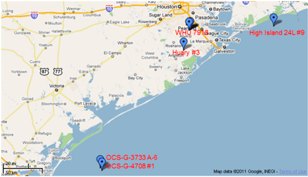
Fifteen thin sections were generated from mudstone cuttings of well OCS-G-3733 A-6 (API: 427034015800). Fourteen thin sections were created using cuttings from well OCS-G-6042 API 4270340281l, which is not shown on the map above, but is located near the Matagorda Island wells. However, the petrographic technicians were unable to sufficiently polish the thin sections due to their unconsolidated nature. The poor quality of the thin sections made petrographic and texture studies very difficult.
The high potential value for seal analyses (i.e., in light of the small number of core samples) necessitated a second attempt to generate polished thin sections from mudstone drill cuttings.
Ten cuttings from a well (API 4270600020) close to the first P-cable survey area were selected within the depth range 4900 to 10105 ft. The samples were moderately polished for SEM examination.
The analyses were carried out using a field-emission SEM, an FEI Nova™ NanoSEM 430, at The University of Texas at Austin. Both Secondary Electron (SE) and Back-Scattered Electron modes were used to show mudstone texture. A system of two, energy-dispersive, X-ray detectors was used in conjunction with SEM to produce elemental maps and consequently, help to identify mineral phases. Back-Scattered Electron images and EDS (energy dispersive spectroscopy) elemental maps were obtained from the thin sections, which yielded useful information on the texture and lithology of the fine-grained portion of the examined samples.
Texture
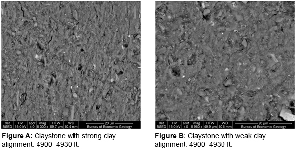
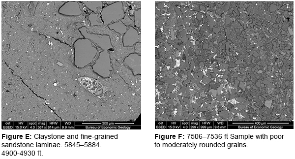
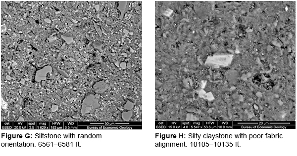
Thin section texture shows large variation. Grain size ranges from clay to fine sand. Silt and sand abundance varies significantly. Figure A shows a claystone with few silt grains while Figure F shows a sample containing over 80% silt grains.
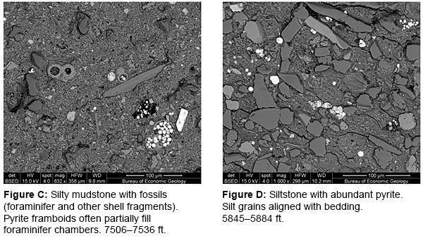
SEM imaging provides a qualitative assessment of fabric alignment. The samples show large variations in degree of fabric orientation. For example, the sample in Figure A shows a high degree of clay alignment in the vertical direction in the image, while the silty claystone in Figure G shows weak clay alignment. Apparently, higher silt/sand content leads to poor alignment. However, silt/sand content is not the only control. For example, Figure A and B are from the same cuttings interval (~30 ft), but the section in Figure A is highly aligned and in Figure B the claystone is poorly aligned. Depth control on clay alignment is not obvious either. Figures A and B show quite different degrees of alignment within the same sample. Figure A is from 4900–4930 ft and it shows better alignment than the deeper samples (e.g. Figures C, G, and H).
Minerology
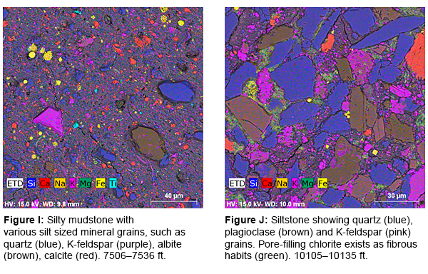
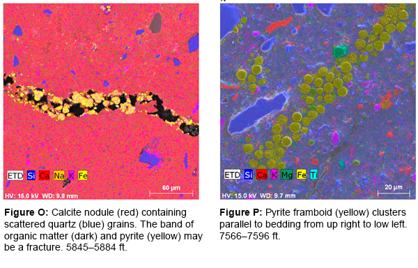
SEM assisted with energy dispersive X-ray detectors was used to make elemental maps of the thin sections, which, to a degree, reveal mineral distribution. Figure I shows a typical elemental map with each element assigned to a distinctive color. With information about the elemental composition and knowledge of the occurrence of common minerals, one can recognize the mineral by the specific color assigned to it. For example, silicon is assigned as blue; so, quartz shows up as blue grains. Purple is assigned to potassium; so purple grains are interpreted as K-feldspar. Calcium (red) is interpreted to indicate calcite. If more than one element is present, the resultant mineral color is a combination of the individual elemental colors. For example, when red is assigned to calcium and yellow to sodium, plagioclase grains show up as brown.
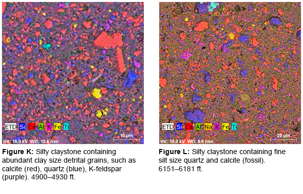
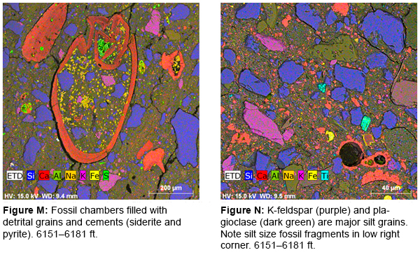
The elemental maps show that the most abundant silt grains are quartz, calcite, K-feldspar and plagioclase. The most abundant detrital grains are quartz (Figure J). Quartz also composes a large proportion of the matrix (Figures I, K). All the samples contain varying amounts of detrital calcite (up to 40%) (Figure K). Calcite is mostly from fossil debris, such as foraminifer and mollusk shell fragments (Figures L-N). However, the clay size grains usually do not show any indications for their origin, and it is difficult to determine whether they are from fossil fragments or from other detrital sources (Figure K). K-feldspar and plagioclase are also abundant (up to 15% locally) (Figures I, J, N). The matrix is mostly composed of illite, chlorite (fibrous, greenish yellow clay platelets in Figure J) and clay-size quartz and feldspar grains.
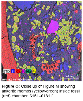
Cementation in the samples is sporadic. Authigenic minerals (those that precipitate during sedimentation) include calcite, pyrite, and ankerite. The sample in Figure O from 5845–5884 ft contains a calcite nodule where authigenic calcite has replaced other minerals and formed a pure calcite area only containing scattered quartz grains. However, calcite cements are not common in other samples, primarily due to the lack of available pore space for precipitation sites. Pyrite usually occurs as framboids and is present throughout the depth range (Figures I, O, P). Sometimes, clusters of pyrite framboids are concentrated in zones, which may be related to fracture or organic-rich layers. Ankerite mostly occurs in fossil chambers (Figures M, Q). Overall, diagenesis does not appear to be significant.
Summary
In the cuttings analyzed, authigenic minerals are in low abundance (< 2%) and do not significantly reduce permeability. Sealing is mainly controlled by clay abundance, fabric alignment and compaction. Claystone and silty claystone with high clay content are present. SEM studies reveal a high degree of compaction and little observable porosity. Clay alignment is variable, but the degree of alignment generally increases with increasing clay content. The clay-rich lithology of the cuttings samples indicates enhanced clay alignment, which in turn indicates reduced permeability. Compaction is probably correlated with depth; however, SEM imaging alone does not show noticeable differences in texture and degree of compaction at different depths. Overall, permeability and capillary entry pressure of the samples are expected to be within the same ranges of measured seal rock core samples from well OCS-G-4708#1.
<< Back to Texas Offshore Miocene Project main page || << view previous Task || view next Task >>

